
The compressor motor jacket plays a vital role in maintaining optimal operating temperature and ensuring the longevity of the motor. Over time, scale, sediment, and other contaminants can build up inside the motor jacket, leading to inefficient cooling and potential equipment failure. This guide provides a detailed, step-by-step compressor motor jacket cleaning procedure, including necessary tools, replacement parts, safety precautions, and best practices to ensure a thorough and safe cleaning process. Regular maintenance of the motor jacket is crucial to avoid operational disruptions and extend the compressor’s lifespan.
Preparation of Compressor motor jacket cleaning procedure (Routine Compressor Maintenance)
(1) Tools and material: A Phillips type screwdriver, a flathead screwdriver, a 10 mm hex wrench, two 17 mm hex spanners, a 500 or 1,000 resistance tester, a torque a scrub brush, a vinyl bag about 30 cm wide at the mouth, a paintbrush, a silicon based coating material, rags, etc.
(2). Replacement Parts
- Jacket cover gasket .
- Jacket cover
- Terminal box gasket
- Orin.
Replacement Parts
When cleaning the compressor motor jacket, some parts may need to be replaced to ensure proper sealing and function after reassembly. These parts include:
-
Jacket Cover Gasket:
This is a sealing ring placed between the motor casing and the jacket cover. It prevents coolant or water from leaking out of the motor jacket. If it’s damaged or swollen, it must be replaced. -
Jacket Cover:
The outer cover or shield that encloses the motor jacket. It may need replacement if it’s corroded, cracked, or deformed. -
Terminal Box Gasket:
This gasket is used to seal the terminal box (where the power wires connect to the motor). It keeps out moisture and dust to protect the electrical connections. -
O-ring:
Small, circular rubber seals (usually two—upper and lower) that fit into grooves around the jacket cover guard. They ensure a watertight seal to prevent leaks at critical joints.
(3) Rustproof Coating: Apply “Rust Primer” once with the paintbrush.
Rustproof Coating
Rustproof Coating: Apply “Rust Primer” once with the paintbrush.
-
Surface Preparation:
Before applying the rust primer, thoroughly clean the surface to remove any dirt, oil, moisture, or old paint. A clean, dry surface ensures proper adhesion of the coating. -
Primer Application:
Use a clean, dry paintbrush to apply a thin and even layer of rust primer. Avoid overloading the brush to prevent dripping or uneven coating. -
Avoid Critical Areas:
Do not apply the primer to areas where gaskets or O-rings will be installed (such as the gasket seat or O-ring grooves). Coating these areas may interfere with sealing and lead to coolant leaks. -
Drying Time:
Allow the primer to fully dry as per the manufacturer’s instructions before proceeding with reassembly. This helps ensure long-term rust protection. -
Reapply if Needed:
If any section looks thin, patchy, or missed, reapply a second light coat after the first one dries. -
Storage & Safety:
Store the rust primer in a cool, dry place. Use in a well-ventilated area and wear gloves and protective gear to avoid skin or eye contact.
Compressor motor jacket cleaning procedure
(1) Cut the control panel power.
- When doing so, please affix a warning label to the control panel so that power isn’t accidentally turned on
- When all that’s being done is cleaning the jacket cover, processing [treating] the refrigerant is not necessary.
(2) Remove coolant from inside the jacket cover.
- Close the coolant intake/outlet vent valve.
- Open the plug (R3/8) in the coolant drain under the jacket cover.
- Remove coolant remaining in the jacket. When doing so, be careful to keep the surrounding area clean.
- Take off the coolant pipes.
(3) Disconnect the power lines.
- Open the terminal box at the front end of the motor. Use the Phillips screwdriver to remove the four screws securing the terminal box and main unit.
- Guiding the power lines, separate the terminal box from the main unit.
- The power lines are labeled A, B, C, V, W, and Z. Check that they are labeled. The same letters are cast on the side of the casing. Check that they agree with one another.
- The power lines are secured and sandwiched between M10 nuts
- Tighten the nut and loosen the nut.
- Always work with the nut tightened.
- If a nut is loosened when the nut isn’t tight, the terminal may rotate inside the device and make contact and cause a short.
- Keep the power lines from coming into contact with water. If they might get wet, cover them with vinyl and take preventive measures so that they don’t get wet.
- Remove the thermostat terminals.
(4) Remove the jacket cover.
- Remove the four 531 bolts and remove the 508-2 jacket cover guard.
- When removing the 508-2 jacket cover guard, remove it after the 498 jacket cover gasket line and 543 O-rings, 2 of them upper and lower, become visible.
- Check them for extent of damage
- Pull out the jacket cover. When doing so, if sediment or deposits or the like have accumulated inside the jacket, thoroughly remove them.
- The 498 jacket cover gasket is inside the jacket cover Take it out and check the extent of damage.
(5) Clean the water channel unit in the motor casing jacket.
- Clean out accumulated sediment, deposits, etc. using a scrub brush or the like
- The tap hole of the lifting bolt in the top is covered with a coating material to prevent corrosion. If necessary, cover it with coating material again.
(6) Paint the jacket’s water channel unit
- Thoroughly wash the surface to be painted so that it is free of oil, and then dry it.
- Paint with rust-preventing paint. (When shipping, use rust primer.) The location to be painted is the outer periphery. surface.
- Be careful not to paint the surface where the gasket cover gasket touches or the gasket cover guard’s O-ring groove. If these do get paint on them, clean all of it off, or it will cause water leaks.
(7) Attach the jacket cover
- Install the 498 jacket cover gasket in the motor casing. When doing so, check that oil doesn’t come into contact with the gasket surface or gasket. Contact with oil causes the casket to swell.
- Insert the jacket cover into the motor casing. The end of the gasket cover becomes the gasket face, so before inserting it,, check that it is free of dents
- Install the 543 O-rings (2) in the 509 motor. casing cover. Coat the O-rings with oil or grease.
- Install the 498 jacket cover gasket in the 508-2 jacket cover guard.
- Check that the O-rings and jacket cover gasket are installed, and install the jacket cover guard. The bolt-tightening torque is 700 kgf-cm.
(8) Connect power lines
- Measure the insulation resistance between terminals and between terminals and casing with the resistance tester. 30 MQ or higher is normal. If the resistance value drops, there may be a short inside the device, so please report this to the factory.
- Connect the power lines after guiding them through the terminal box gasket and terminal box in sequence.
- Connect so that the power line labels match the letters cast on the casing.
- Connect the thermostat terminals. There is no left or right. Connect two.
- When all the connections are done, please measure the insulation resistance again.
(9) Attach the Terminal Box
- Ensure all power connections inside the terminal box are secure and correctly matched to their labels (A, B, C, V, W, Z).
- Double-check that the terminal box gasket is properly seated to prevent moisture or dust from entering.
- Tighten the screws evenly in a diagonal pattern to maintain even pressure and sealing.
- Inspect the terminal box cover for any cracks or wear before closing.
(10) Connect the Coolant Pipes
- Clean the pipe ends and connection ports to remove any debris before installation.
- Ensure all fittings are properly aligned to avoid cross-threading or leakage.
- Use appropriate sealing materials (like thread seal tape or gaskets) where required.
- After connection, secure the pipes to prevent vibration or movement during compressor operation.
(11) Run Coolant Through and Check for Leaks
- Slowly introduce coolant into the system to avoid pressure surges.
- Use a flashlight and clean rags to inspect all joints and fittings for any signs of leaks.
- If any leakage is detected, tighten connections or replace gaskets/O-rings as necessary.
- Monitor for a few minutes to ensure the system maintains a stable pressure with no dripping.
(12) Adjust Coolant Flow Through Condenser Oil Cooler and Motor Jacket
- Ensure the coolant flow is balanced between the motor jacket and condenser oil cooler for efficient thermal management.
- Use flow control valves or flow meters (if available) to fine-tune the flow rate.
- Refer to equipment specifications for optimal flow rates and temperatures.
- After adjustment, monitor coolant return temperature and system performance to confirm proper cooling efficiency.
(13) power up the control panel and remove the warning label
If the motor jacket unit operates with water of poor quality or not enough water, scale will accumulate and cause cooling problems. please clean it properly once a year before water temperature rises
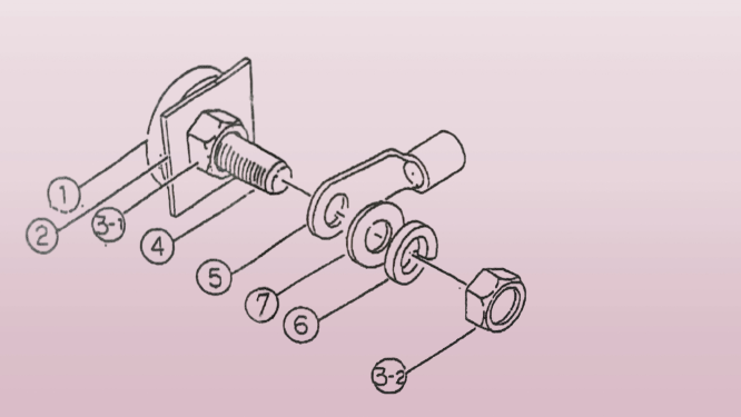
When removing the removingpower line tighten the nut 3-1 and loosen the nut number 3-2. If only is loosened, terminal 4 may rotate and cause an internal short
Similarly, when tightening nut 3-1, tighten nut 3-2. The nut-tightening torque is 145 kgf cm-199 kgff-cm. Tightening with torque greater than this will deform the terminal

When removing the power line, tighten terminal 4 and then loosen hex 3. Do the same when attaching thetightening torque is 145 kgf cm-199 kgf-cm
Conclusion
Cleaning the compressor motor jacket is not just a routine maintenance task—it’s a preventive measure against costly failures and inefficiencies. By following the proper cleaning steps, using the right tools, applying rustproof coatings, and ensuring secure power and coolant connections, you can enhance equipment performance and operational safety. Annual cleaning, especially before rising water temperatures, helps prevent scale buildup and ensures continuous, reliable operation of the compressor system.
Summary
Tools & Materials: Phillips and flathead screwdrivers, hex wrenches, spanners, resistance tester, paintbrush, rustproof coating, scrub brush, etc.
Parts Required: Jacket cover gasket, terminal box gasket, O-rings, and jacket cover.
Procedure: Involves disconnecting power, draining coolant, removing the jacket cover, cleaning internal surfaces, applying anti-rust coating, reassembling parts, and testing for leaks and electrical safety.
Precautions: Use warning labels, avoid overtightening, prevent water contact with power lines, and ensure gasket surfaces remain oil-free.
Recommendation: Perform jacket cleaning annually to avoid scale buildup and overheating issues.
FAQs
1. Why is it important to clean the compressor motor jacket?
Cleaning prevents scale buildup and sediment accumulation, which can impair cooling efficiency and lead to motor overheating or failure.
2. How often should the motor jacket be cleaned?
It is recommended to clean the compressor motor jacket once a year, especially before high water temperature seasons begin.
3. What should be done before starting the cleaning procedure?
Cut the control panel power, affix a warning label to prevent accidental power-up, and gather all necessary tools and replacement parts.
4. What rustproof material should be used after cleaning?
Use a rust-preventive coating like “Rust Primer” on the motor casing’s outer periphery to protect against corrosion.
5. How can you ensure the power lines are correctly reconnected?
Ensure power lines A, B, C, V, W, and Z are labeled and match the markings on the motor casing. Check insulation resistance before and after reconnection.
6. What is the recommended torque for tightening the terminal nuts?
Tighten to a torque of 145–199 kgf-cm. Overtightening can deform terminals and cause electrical issues.
7. What are the signs that the jacket cover gasket needs replacement?
If the gasket is swollen, cracked, or shows signs of oil contact or physical damage, it must be replaced during reassembly.